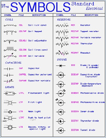

Ideal source includes an ideal voltage source and ideal current source.Source is a part of a field-effect transistor from which carriers flow into the inter-electrode channel.Battery is a container consisting of one or more cells, in which chemical energy is converted into electricity and used as a source of power.Cell is a device containing electrodes immersed in an electrolyte, used for generating current or for electrolysis.

Earth electrode is a metal plate or other conducting elements of electricity partially buried in the earth to constitute and provide a reliable conductive path for the fault current to the ground.Therefore, anyone who knows of electrical and electronic circuits can read, understand, and build electrical diagrams quickly. You can depict a complex electrical circuit with the standard and simplified electrical symbols. Whether you are a novice or a professional engineer, these basic symbols can help create accurate electrical and circuit diagrams in minutes. Hope this helps.Basic electrical symbols contain earth electrode, cell, battery, resistor, etc. The libraries that come with packages is always lacking, however, you should be able to find suitable electrical/electronic symbols that are DXF or DWG type files all over the internet to add to your library. You mentioned schematics, and all of the above mentioned can do schematics, but for parts libraries, you would probably want DraftSight or Autocad. If pricing is an issue, DraftSight is the less expensive of the 3 that I mentioned. Visio will take in DXFs of the elevations, however, as well as Autocad and DraftSight. MS Visio can do this, but it is not as concise as Autocad or DraftSight. However, in order to complete your interconnection diagram, you will need a 2d program to do so. The other side of the coin is to use a 3d modeling program, such as SolidWorks, to model your different interfaces and then pull elevations from different sides as needed in 2d. With that said, Autocad will do nicely for these drawings, as well as Dassault Systems (the people who make Solidworks) has a 2d package called DraftSight that is excellent. These elevation drawings can often be provided by the different manufacturers of the product, however, in many cases, you will have to draw the elevations yourself and add them to your library. There will be no drawing packages that have libraries of your particular interfaces. It appears you are drawing the elevations of different equipment that you are interconnecting. The drawing that you are showing is a basic interconnect drawing.


 0 kommentar(er)
